How to Make Screw Jack in SolidWorks
In this comprehensive tutorial, we will delve into the process of creating a screw jack using the popular 3D CAD software, SolidWorks. By the end of this guide, you’ll have a clear understanding of how to use SolidWorks to design and assemble your own screw jack.
Understanding Screw Jack
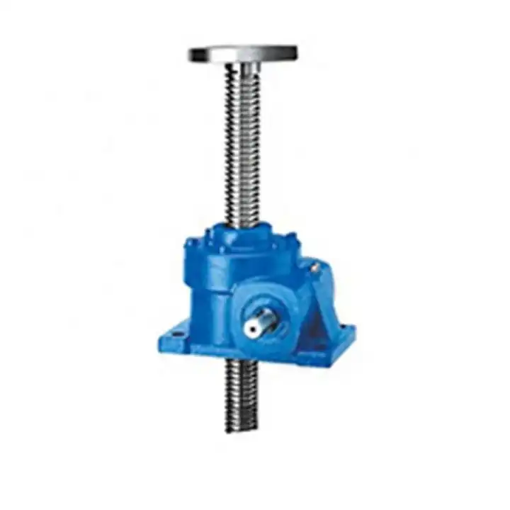
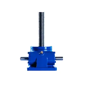
Before we dive into the step-by-step guide, let’s take a moment to understand what a screw jack is. A screw jack is a mechanical device that is used to lift heavy loads via a lead screw. It’s a simple machine that effectively transforms rotational motion into linear motion. The design of a screw jack may seem complex at first, but with SolidWorks, you can easily design one on your own.
Launching SolidWorks
The first step in creating a screw jack in SolidWorks is to launch the software. If you haven’t installed it yet, you can download it from the SolidWorks website. Once installed, open the program and familiarize yourself with the user interface. You’ll find various tools and options that are essential for your screw jack design.
Designing the Screw
With SolidWorks open, it’s time to start creating the components of your screw jack, the first of which is the screw. To do this, navigate to the “New” option in the file menu and select “Part”. Use the “Helix and Spiral” feature to create the spiral path of the screw. You’ll need to specify the parameters such as the pitch, diameter, and height to suit your requirements.
Creating the Nut
Following the screw, the next component to create is the nut. This is the part that moves up and down the screw when it rotates. To create the nut, you’ll need to use the “Extruded Boss/Base” feature and the “Hole Wizard” feature to make the hole in the middle of the nut. Make sure the diameter of the hole matches the diameter of the screw.
Assembling the Parts
With the individual components created, it’s time to assemble them together. To do this, navigate to the “New” option in the file menu and select “Assembly”. Here, you’ll add the screw and the nut and use the “Mate” tool to align them properly. Remember to add a “Screw Mate” to ensure the nut moves along the screw when it rotates.
Adding the Handle
The final component to add to your screw jack is the handle. This is the part that is used to rotate the screw. To create the handle, navigate back to the “Part” workspace. Use the “Extruded Boss/Base” feature to create the main body of the handle and the “Revolved Boss/Base” feature to create the grip. Once created, add it to your assembly and use the “Mate” tool to attach it to the top of the screw.
Simulating the Motion
With your screw jack fully assembled, you can now simulate the motion to see it in action. To do this, navigate to the “Motion Studies” tab and select “New Motion Study”. Here, you can define the rotation of the handle and observe the motion of the nut along the screw.
Final Thoughts
Creating a screw jack in SolidWorks may seem like a daunting task, but with this step-by-step guide, you should be able to design one with ease. Remember to always check your parameters and ensure everything is properly mated in your assembly. Happy designing!