How to Make Screw Jack in Solid Edge
Developing a screw jack in Solid Edge, a leading 3D CAD software solution, is an essential skill for mechanical engineers and designers. This article offers an in-depth, step by step guide to creating a screw jack in Solid Edge. It covers everything from the preliminary stage of setting up the project to the final stage of rendering and exporting the finished model.
Understanding the Basics of Screw Jacks
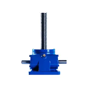
Before diving into the process, it’s worth understanding what a screw jack is and its importance in mechanical engineering. A screw jack is a mechanical device that converts rotational motion into linear motion. It’s commonly used to lift heavy weights, such as vehicles or machinery, with minimal effort.
Getting Started with Solid Edge
Solid Edge is a versatile software tool that’s perfect for creating 3D models of mechanical parts. It supports parametric modeling, direct editing, and simplified design processes, making it an excellent choice for both beginners and experienced CAD users. But before you can start designing your screw jack, you need to familiarize yourself with the software’s basic functions and interface.
Creating the Screw Jack Body in Solid Edge
The first step in creating a screw jack in Solid Edge is designing the body. This involves creating a new part file, setting up the necessary parameters, and using the software’s sketching tools to draw the basic shape of the jack. You’ll also need to use the extrusion and revolution features to give the body its three-dimensional form.
Designing the Screw and Nut Components
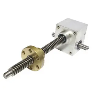
Once the body of the screw jack is complete, the next step is to design the screw and nut components. These are the parts that allow the jack to convert rotational motion into linear motion. Like the body, these components are created using the sketching and extrusion tools in Solid Edge. However, they also require the use of the helix and thread features to create the screw’s spiral shape and the nut’s internal threads.
Assembling the Screw Jack
After designing all the components, it’s time to assemble the screw jack. In Solid Edge, this is done in the assembly environment, where you can position and connect the components using constraints and mates. You’ll also have the chance to test the jack’s motion and make any necessary adjustments to ensure it works correctly.
Finishing Touches: Applying Materials and Rendering
The final steps in creating a screw jack in Solid Edge involve applying materials to the components and rendering the model. Applying materials not only gives the model a realistic appearance but also allows you to perform stress and strain analyses. Rendering, on the other hand, produces a high-quality image or animation of the model, which can be used for presentations or marketing materials.
Exporting Your Screw Jack Model
Once you’re satisfied with your screw jack model, the last step is to export it. Solid Edge offers several export options, including 2D drawings, 3D PDFs, and various CAD file formats. Choose the option that best suits your needs and follow the software’s prompts to complete the export process.
Conclusion
Designing a screw jack in Solid Edge may seem complex at first, but with patience and practice, it becomes a manageable task. The key is to understand each step of the process and to use the features and tools in Solid Edge effectively. So whether you’re a novice CAD user or an experienced designer, this guide provides a comprehensive overview of how to make a screw jack in Solid Edge.