Mastering CAD Bevel Gear: Your Comprehensive Guide
Understanding CAD Bevel Gear
In the realm of mechanical engineering and design, CAD (Computer-Aided Design) for bevel gears is an essential skill. This comprehensive guide provides detailed insights into the process of designing and creating Bevel Gears using CAD tools.
Our Premium Bevel Gear Production
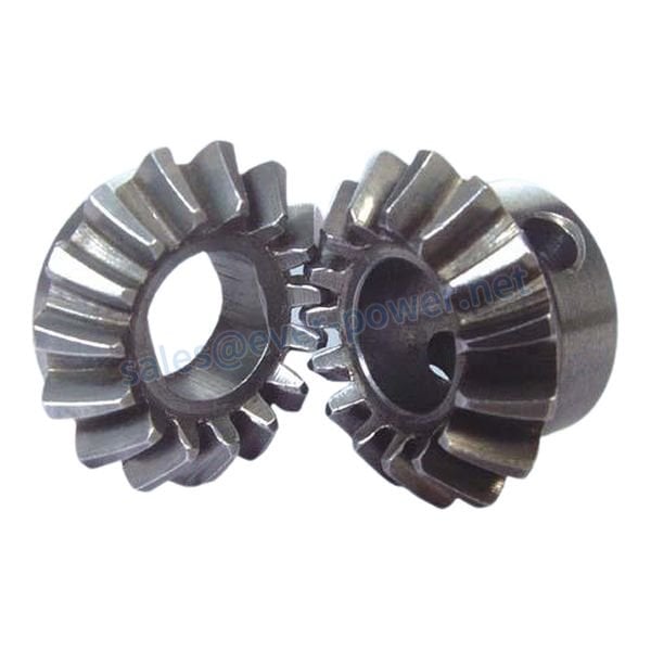
As industry leaders, we pride ourselves on producing high-quality Bevel Gears. Here are some highlights of our product:
- Highly durable
- Precision-engineered
- Customizable to specific requirements
- Manufactured using advanced technology
- Competitive pricing
Different Types of Bevel Gears and Their Features
There are various types of Bevel Gears, each with specific features.
Straight Bevel Gear
Straight Bevel Gears are the simplest form with straight and tapered teeth. They are used in situations where the direction change is more significant than speed.
Spiral Bevel Gear
Spiral Bevel Gears have curved and oblique teeth. They are known for their smooth operation and are used in high-speed applications.
Zerol Bevel Gear
Zerol Bevel Gears are similar to straight bevel gears, except they have curved teeth.
Spiral Zerol Bevel Gear
Spiral Zerol Bevel Gears are a hybrid of spiral and zerol gears. They are quieter and can handle more load.
Selecting the Right Bevel Gear
When choosing a Bevel Gear, consider the following parameters:
- Module: This is essentially the pitch diameter divided by the number of teeth.
- Number of Teeth: This affects the gear’s size and strength.
- Gear Ratio: This is the ratio between the ‘drive gear’ (the one directly receiving force) and the ‘driven gear’ (the one that is driven by the ‘drive gear’).
- Pitch: This is the distance between corresponding points on adjacent teeth.
- Gear Material: The material used to make the gear affects its strength, durability, and resistance to wear.
- Precision Grade: This refers to the gear’s manufacturing accuracy.
- Load Capacity: This is the maximum load the gear can handle.
Bevel Gears Manufacturing Process
The manufacturing process of Bevel Gears involves several steps:
- Design and Engineering: This involves creating the gear design using CAD tools.
- Material Selection: The appropriate material for the gear is chosen based on the gear’s requirements.
- Processing and Grinding: The gear is then cut and ground to shape.
- Heat Treatment: This process strengthens the gear and increases its durability.
- Cleaning and Inspection: After heat treatment, the gear is cleaned and inspected for defects.
- Assembly and Machining Accessories: The gear is then assembled and any necessary machining is done.
- Surface Treatment and Coating: The gear is then treated and coated to increase its resistance to wear and corrosion.
- Final Inspection and Quality Control: The finished gear is then inspected one last time to ensure it meets all specifications and quality standards.
Our Other Gear and Gearbox Products
In addition to Bevel Gears, we also offer a wide range of other gear and gearbox products, including worm gear, helical gear, spur gear, gear rack, worm gearbox, planetary gearbox, and helical gearbox.
About Our Company
With a fleet of advanced production and inspection equipment such as CNC Gear grinding machine, gear measuring machine, CNC gear shaper, machine center, CMMS, and Torque test system, we are dedicated to producing top-quality gears and gearboxes. Our commitment to excellence, coupled with our international certifications and customizable services, makes us a trusted partner in the industry. Furthermore, our exceptional after-sale services ensure our clients’ needs and concerns are always addressed promptly and professionally. Partner with us today for all your gear and gearbox needs.